FlipSide SMT Stencil Printer

Specifications

  • Stencil Style: Stainless Steel Frameless
  • Max stencil size: 230mm x 290mm (9.06″ x 11.42″)
  • Fixture bed size: 220mm x 340mm (8.66″ x 13.39″)
  • Bed T-slot size: Misumi 2020 profile w/ 6mm slot
  • X/Y adjustment range: ±15mm (±0.59″)
  • Nominal Z-height: 18.63mm (0.73″)
  • Z adjustment range: ±2.5mm (±0.1″)
  • Footprint: 355mm x 500mm (13.98″ x  19.69″)
  • Parts Cost: $201.27 (USD, excluding filament)

Assembly Instructions

How To Use

Motivation

Circuit board assembly can get pretty tedious, especially nowadays where devices are only available in tiny surface-mount packages. Thankfully, soldering components down is made a bit easier with solder paste and solder paste stencils. There’s a “cheap and cheerful” technique of applying solder paste which involves taping some spare PCBs down as an alignment jig and taping your stencil down on one edge so that it can still flip up when you’re done applying solder paste. Okay lol I know that didn’t make much sense, so here’s a pic of what I’m talking about:

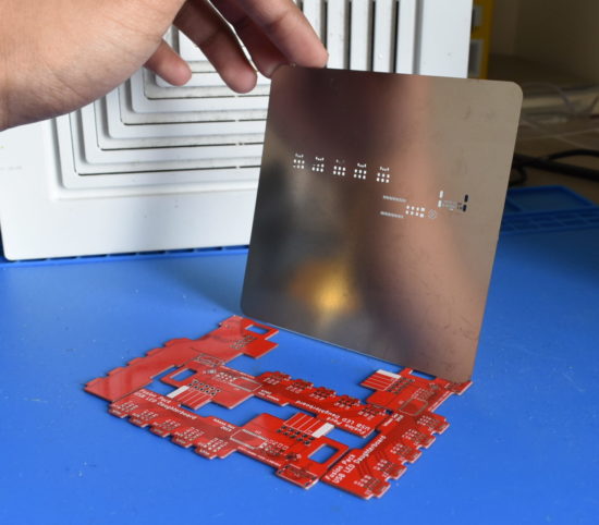
Kinda like this but imagine that I did a decent job of aligning the stencil and taping down the boards
(trust me I try my best when I’m actually trying to solder down a board)

But the thing is, I still suck at this technique. I can’t for the life of me align the solder paste stencil with respect to the rest of the circuit board and hold down the stencil without having it shift on me. And if I get that far, I can never lift up the stencil without smearing the solder paste I shoddily laid down.

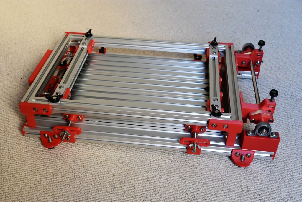
Rewind to a couple months ago, where I stumbled across this video about a manual “frameless stencil printer” by Fortex. “Sweet!” I thought, and went to check how much they ran for.
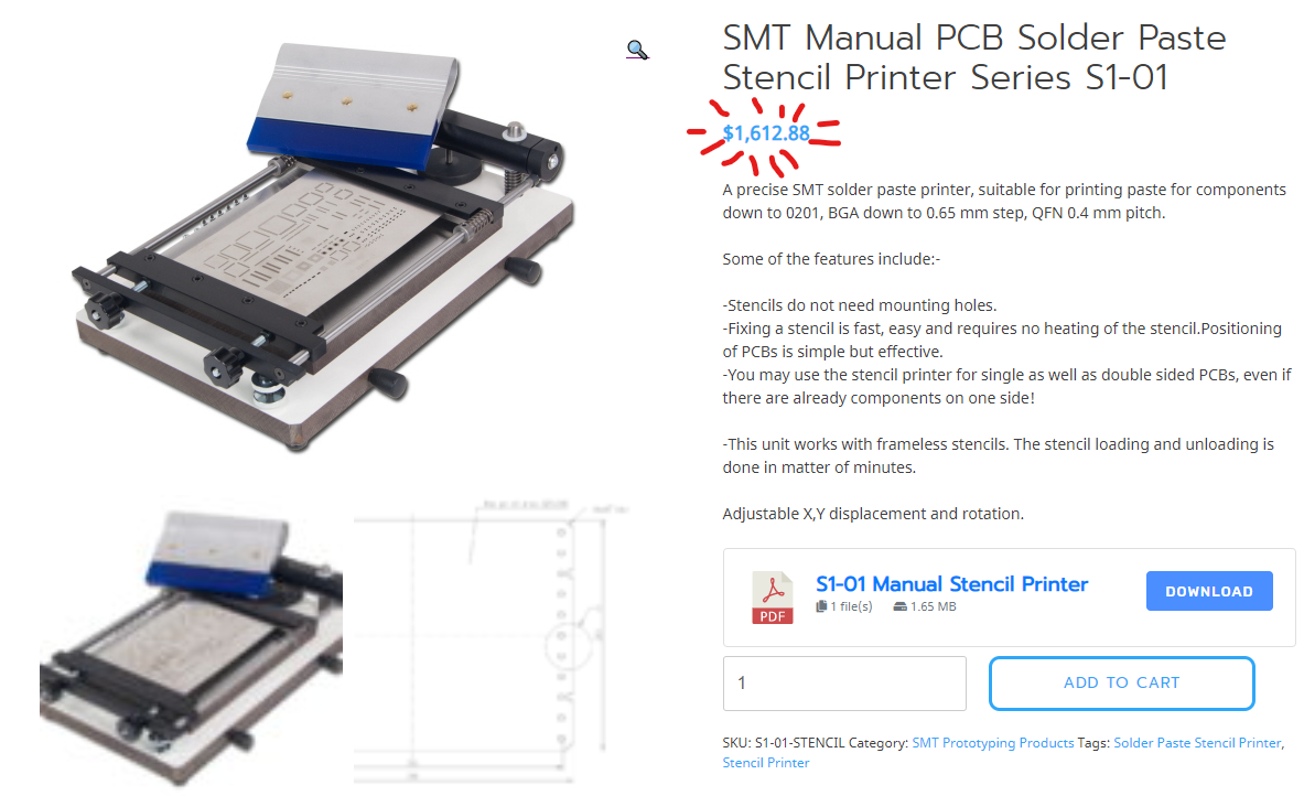
Name-brand Fortex Frameless Stencil Printer

what.

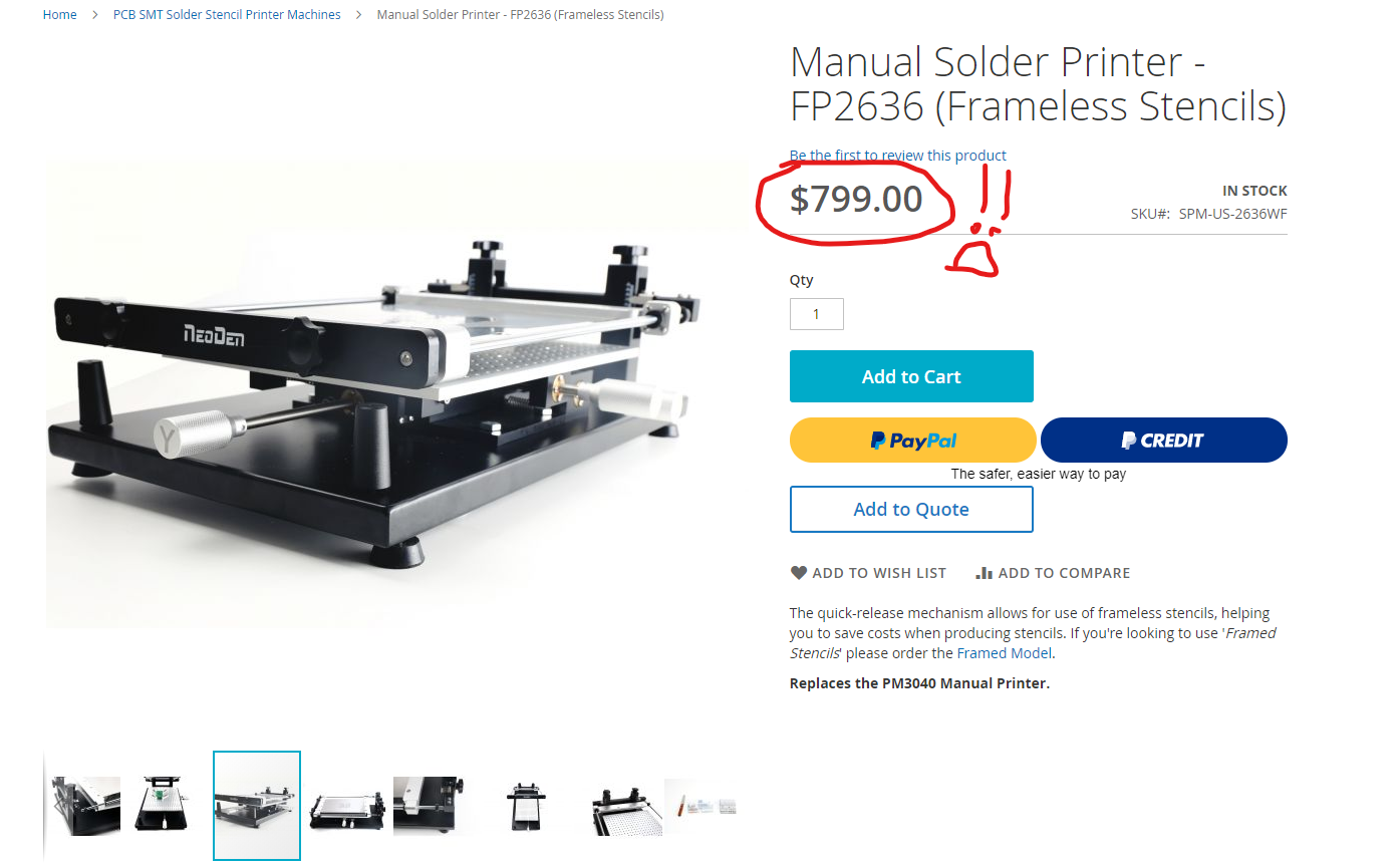
In fact, the cheapest frameless SMT stencil printer that I could find was still ridiculously expensive, sold by a company called Neoden USA.

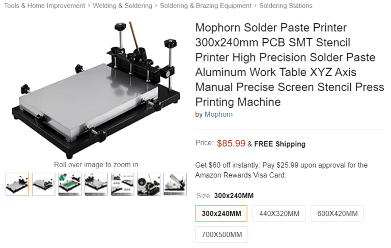
Okay, okay, I know some of you guys are saying, “wait there are some super cheap ones on Amazon for like $85 delivered, why don’t you get one of those?” I considered getting one of these for a while, but three reasons kept me from pulling the trigger:

The cheapest non-sus stencil printer I could find on Amazon
  • Fixturing stuff onto their beds require magnetic standoffs which aren’t included in the package. I’d have to make my own out of some small neodymium disk magnets and 3D printed parts which isn’t a huge deal. 
  • Their adjustment/trim mechanisms seem a little fiddly. To move your workpiece left/right and rotate it, you need to simultaneously tighten and loosen the thumbscrews. This isn’t a huge deal, but I’d much prefer turning a single screw to move the platform around, and lock it in place with a separate mechanism.
  • And the main reason, they require you to buy framed stencils. These take up significantly more storage space, and cost about $10 more (including shipping) for an average-sized board at the cheapest PCB suppliers. I could design my own frameless stencil holder, but at that point I might as well design the entire stencil printer my way–the base plate and adjustment mechanism are the easy parts.

So that’s what I did. For a little over $200 I designed my ideal stencil printer. I’ll go into a bit more of the design details in the next section.  

Development and Design Highlights

I’ll admit, there’s nothing toooo fancy about FlipSide–after all it’s a purely mechanical device with only one major moving part, four if you want to be generous. However, I’ll discuss some of the major features and design elements that I’m proud of, or at least gave a bit of thought to.

2020 Aluminum Extrusion Construction

I really love aluminum extrusions. They’re sturdy and rigid, easy to mount stuff to, and most importantly, you can get them in configurable lengths from suppliers like Misumi. This last part is super important, since at the time I was designing this, the only metal cutting tool I had was a hacksaw. In fact, I designed FlipSide to minimize the number of manual cutting/shaping operations I’d need to do. 

OpenRail as a Stencil Clamping Mechanism

Finding a way to clamp a frameless stencil took a little bit of thinking. Most expensive commercial stencil printers used a custom-machined aluminum clamping mechanism which would be impossible to replicate with the tools I had access to. Cheaper (but sketchier) alternatives used drilled extrusions would have been doable, but would require me to 3D print drill jigs and manually drill the holes. And I’m not even sure how effective such a clamping mechanism would be, given the geometries of typical structural aluminum extrusion.

A while ago, I had stumbled across OpenRail, an extrusion profile made by OpenBuilds traditionally used for linear motion. However, I realized it would be awesome for this project for two reasons:

  1. The profile came together at a sharp(ish) point, which would concentrate clamping pressure on the stencil.
  2. These extrusion sections came pre-drilled (or “pre-slotted” I guess) with mounting slots. And thankfully, the upper radius of the slot would allows the edge of the openrail section to clamp on another piece of 2020 profile.

I’d still have to cut this extrusion to length. Fortunately, however, the profile is fairly thin and cutting it with a hacksaw wouldn’t be too much of a problem. 

X/Y/Theta Trim Adjustment

Almost every stencil printer uses some sort of screw mechanism to adjust the X, Y and theta (the angle) of the bed where the PCB sits. The challenge lied on the implementation specifics.

In the above section, I complained about the implementation of the trim mechanism in the Amazon stencil printers–they lock the bed in place and move it around with the same set of screws, meaning both of those actions (trimming and locking) are fiddly. Separating the mechanisms that lock the bed and move it around, then, should make the entire stencil printer easier and more enjoyable to use. Fortunately, that’s pretty easy to do. 

To trim the bed, FlipSide would have some long M5 bolts paired with springs and wingnuts. Tightening the wingnuts would pull the bed closer to the wingnut bracket location, and loosening them would do the opposite. The slots in these brackets allow this mechanism to work without binding across the bed’s entire range of motion.

Spring selection also took a bit of thought. Initial designs used compression springs between the wingnut bracket and bed to “push away” the bed. However, springs that could extend over 30mm couldn’t fit in that location. Instead, I used (in the current design) extension springs that pull the bed away from the bracket.

The bed locking mechanism is dead simple and honestly shouldn’t really need too much explanation. It’s just some screws that clamp down onto some flanges and hold it in place with respect to the bed. For a little bit of tool-less convenience, I designed and printed some “wingscrew adapters” that let me tighten everything up by hand. Printed in black to make them stand out (and to look good 🙂 )

Z Height Trim Adjustment

This is probably the part of FlipSide that I’m proudest of. The Z-height adjustment mechanism is rigid and precise, all while being cheap and minimizing part count. However, my first design for the z-axis was far from ideal.

In fact, I gave up part-way through my first design, realizing it was no good. It was a bolt/thumbscrew/spring mechanism, not too unlike the X/Y/Theta trim mechanism, and some current stencil printers on the market. The part count for this mechanism was going to be extremely high, and would involve spec’ing springs, which is something I could never get right the first time (I don’t have any intuition about how to choose spring constants lol). The actual hinge mechanism would consist of some bearings press-fitted into 3D printed parts, rolling along 3D printed axles, which would be a recipe for disappointment. 

After a bit of thinking, I remembered that the consumer 3D printing boom has made precision hardware like pillow block bearings, shaft clamps, and shafts cheap and accessible. Using these parts in my hinge would mean that I wouldn’t need to print any high-precision bearing snap-fits, and would have the rigidity of metal parts, so I did just that. FlipSide’s new hinge revolves around (hah get it) KP08 pillow block bearings, SHF8 shaft clamps, and an 8mm shaft, all of which are cheap and found through many retailers.

The challenge now was how to integrate a Z-height adjustment mechanism into this hinge design

And that’s basically it! FlipSide is a pretty simple beast, but hopefully a useful one nevertheless!

Lessons Learned

Given my set of design and manufacturing constraints, I’m really satisfied with the overall design of FlipSide. During the development, however, I had to iterate a handful of parts multiple times simply because I forgot to add tolerances. However, my main takeaway is that I’m going to avoid using Hidden Corner Brackets to bolt extrusions together (pictured). These guys were really fiddly to install, and when you tightened them down, they’d shift the extrusions around, creating gaps and ruining all your effort in setup and alignment of your extrusions. 

Image Gallery